Solar Power
Beaming Demonstration Unit
Parts Assembly Instructions
Parts Assembly Instructions
By Phil Mills, Space Frontier Foundation and The Moon Society
May 14, 2008
| Main Mirror Assemblies | Center Mirror Assembly | Wood & Wire parts |
| Working Parts | Overall Assembly Directions | Shipping & Packaging |
| Online Kit Home |
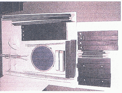
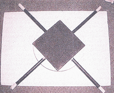
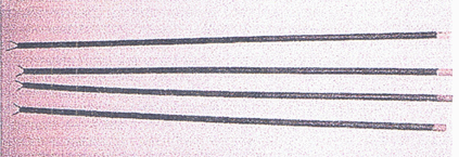
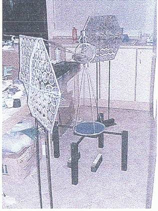
Fig 1) Solar Power Satellite Model and Stand Parts
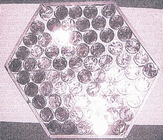
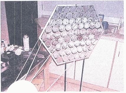
Fig 2) Right side main mirror assembly (note "R") on the top side of the assembly
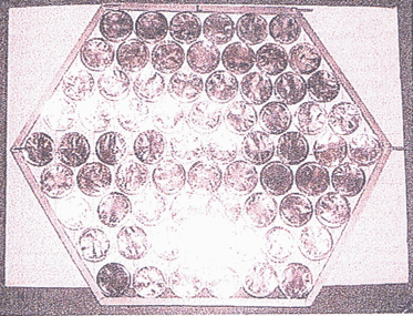
NOTE: See Instructions for creating the Main Mirror Assemblies
Fig 3) Left side main mirror assembly (note "L") on the top side of the assemblyAdditional Tools and materials needed to complete Assembly.
To complete the model and install components of the Power Beaming assemblies, it will be necessary to drill a number of holes.
A small size (depending on the size of screws used) drill bit and power tool is therefore recommended.
Screw drivers.
Tape such as Duck tape may be needed to give a firm fit to the large wood dowels fitted into the stand center block and the legs.
Line drawings of the Solar Power Satellite are included. These are used to identify the Support Rods.
Rods Part "E" and "F" are deleted from the model.
Step 1) Fitting of the Transmitter Antenna Assembly to the Stand Center Block.
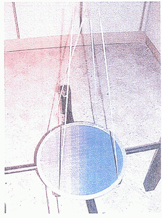
Before the model assembly can begin, it is necessary to fit the Transmitter Antenna Assembly and its associated components to the Stand Center Block. The Antenna is fitted to the underside of this Block, the blue Solar Cell Disc is already fitted to the upper side. The associated electronics can be fitted to a side of the block.
Step 2) Fitting of the Large Dowels into the Stand Center Block.
The large dowels are fitted into the Stand Center Block. Use Duck tape partially wrapped around the ends of the dowels to ensure a good fit. Ensure the unpainted end is fitted in the block, the black end of the dowel fits in the leg.
Fig 4) Stand Center Block and Large Dowels. The Transmitter Antenna is fitted to this side of the Block. Note "Duck" tape wrapped partially around the ends of the dowels to ensure a good fit.
Fig 5) The Large Dowels fitted in the Stand Center Block
Step 3) Assembly of the legs to the dowels.
Select the required legs needed depending on which option is needed.
Option 1 is the short legs.
Option 2 is the long legs.
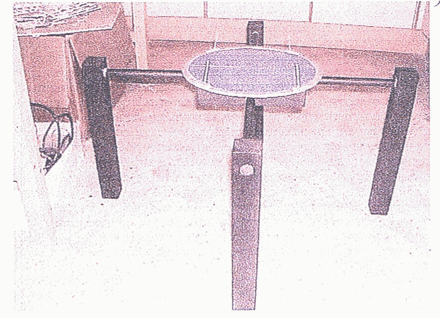
Fit the legs to the dowels in the drillings near the top of the legs. The dowels should be flush in the holes. The Center Stand should now stand on its own and is fully assembled.
Fig 6) The Center Stand Fully Assembled. Note the Blue Solar Cell Disk.
Step 4) Assembly of the Receiving Antenna Stans and selection of the required shims to adjust the height of this Antenna.
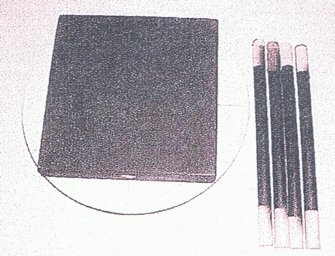
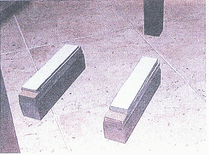
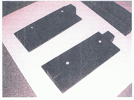
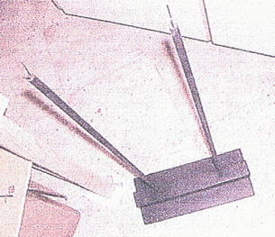
Fig 7) The Receiver Antenna Stands and associated shims.
Select the required stands, Option 1 is the short length blocks and Option 2 is the long length blocks.
To attach the Antenna, holes need to be drilled in the blocks to take the screws. To adjust the height of the Antenna and vary the gap between the two Antenna's to obtain the required "best operation"' shims are provided. These are the strips of wood and plastic provided. Once the required gap is achieved using the shims as necessary, holes should be drilled through the selected shims to secure them to the stand along with the Antenna.
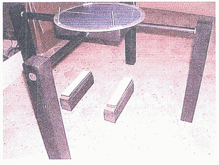
Associated electronics may also be attached to the stands as required. The Power transmission side of the model is now complete.
Fig 8) The complete Center Stand and Receiver Antenna stand and shims.
Step 5) Fitting of the Center Mirror Assembly Support Rods.
Select the 4x1/8th inch diameter Rods with the letter G identifying them. These are fitted to the 4 corresponding tubes located on the edge of the Solar Cell Disk
Fig 9) Center Mirror Assembly Support Rods fitted to the Solar Cell Disk.
Identifying Letters attached to clear plastic is used to identify the rods and can be seen in the photo. These particular rods are identified as G. See enclosed line drawings. Because of the two option heights, there are correspondingly tow different lengths of thin dowel supplied to support both options. The short length dowels Option 1, and the longer length Option 2.
Step 6) Center Mirror Assembly Fitting
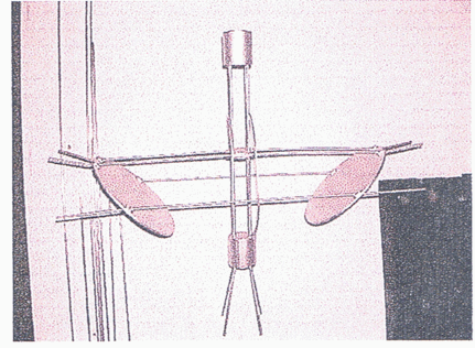
The Center Mirror Assembly is fitted to the top of the Center Mirror Support Rods. Ensure that the mirrors on the Center Mirror Assembly are located left to right on the display table and not front to back.
Step 7) Main Mirror Assembly Stands.Fig 11) Center Mirror Assembly fitted to its support rods.
- Fig 10) Center Mirror Assembly, shown left to right. The 4 tubes located on the lower cylinder are fitted to the Support Rods.
Before the left and Right Main Mirrors can be fitted to the Model, their corresponding stands have to be assembled first, to support the Mirror assemblies. The Mirror Stands consist of wooden blocks attached to melamine sheets, with 2 thin dowels inserted vertically in the block. These dowels have two thin brass tubes inserted into the top ends, angled in the form of a Vee. The Mirror Assemblies rest in the Vee along the lower edge of their frames. The stands are angled at 45 degrees to the model as are the Mirror Assemblies.
Fig 12) The wooden blocks of the two Mirror Assembly standsStep 8) The Center Mirror Assembly to Main Mirror Assembly connecting rods.
Fig 13) The Thin Dowel Mirror support. Four are needed for each option. Note the V notches at the top in which the Mirror Assemblies sit. Select the correct option of Dowels and insert these in the blocks. Make sure the Vee notches are lined up the same way so as to take the Mirror frame. The Stans are ready for the Mirrors.
Fig 14) A complete Main Mirror stand. Note the Vee notches angled the same way.
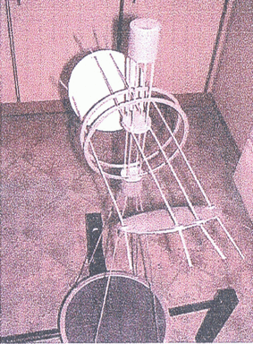
These are 4 different length 1/8th inch diameter brass or aluminum tubing on each side. They are identified with lettering A, B, C, D. See enclosed line Drawing. The rods are inserted into the corresponding tubes or rods on the Center Mirror Assembly. Rod A connects the upper left of the Right Mirror Assembly, and the upper right of the Left Mirror Assembly. Rod B connects the upper right end of the Right Mirror Assembly and the upper left of the Left Mirror Assembly. Rod C connects the mid rear connection on the Right Mirror Assembly and the mid rear connection of the Left Mirror Assembly. Rod D is the longest and connects the mid forward on the right Mirror Assembly and the mid forward of the Left Mirror Assembly.
Fig 15) View from the left of the Center Mirror Assembly with the Connecting rods fitted in place. Note the reflection on the Center Mirror of the Blue Solar Disk caused by the flash photography!
Step 9) Fitting the Main Mirror Assemblies.
The Main Mirror Assemblies are fitted to their connecting rods with angled tubes which are located on the frames of the Mirror Assemblies. The Main Mirror Assemblies are handed Left and Right and are marked correspondingly with "L" and "R", on the top center of each Main Mirror Assembly Frame.
Fig 16) Close up of the Left Main Mirror Assembly showing the "L" located on front side of the upper part of the frame. Correctly locate the Mirror Stands. Carefully balancing the Mirror Assemblies in the Vee notches, locate the connecting rods in the Mirror Assembly tubes. It is best to work from rear to front and complete each side in one operation. Once the Main Mirrors are fitted, the whole model may be adjusted slightly if needed to get the correct angles to the Mirrors and to straighten or adjust any connecting rods.
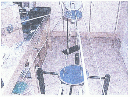
Fig 17) The completed assembly of the Solar Power Satellite Mode.'
NOTE: See Instructions for creating the Main Mirror Assemblies (on separate page)
© 2008-2009 The Moon Society


